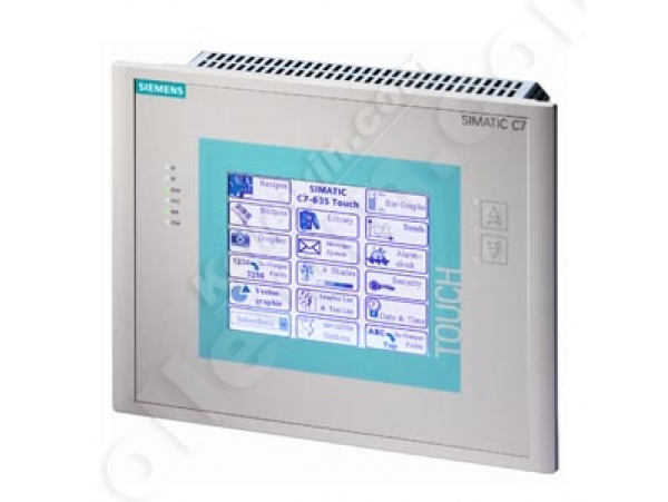
6ES7635-2EB01-0AE3 C7-635 TOUCH, 24 DI, 16 DO, 5 AI, 2 AO

Product Code: 6ES7635-2EB01-0AE3

Availability: In Stock

Price: $1,459.05
  
 
Artikelnummer 6ES7635-2EB01-0AE3
Operator control and monitoring
Alarms Fault messages, operating messages (no buffer)
Operating / fault messages
● Operating messages
— Operating messages, max. total number of operation and fault messages
— Number of entries in operational log, max. not retentive
● Fault messages
— Number of fault message, max. total number of operation and fault messages
— Number of entries in fault message buffer, max. not retentive
Recipes
● Data records per recipe, max. limited due to storage medium
● Recipe data memory, max. expandable using Compact Flash Card (CF-Card)
Display
Design of display STN, CCFL backlit, 5.7" blue mode (4 blue tones)
Control elements
Keyboard
● Type Touch (resistive/analog)
Input current
Current consumption, typ. idling
Inrush current, max. for 70 ms
Digital outputs
● from load voltage L+, max. per group
Memory
Compact Flash Card Optional
Backup
● present Guaranteed by MMC (maintenance-free)
CPU-blocks
DB
● Number, max. DB 0 reserved
FB
● Number, max. see instruction list
FC
● Number, max. see instruction list
OB
● Number, max. see instruction list
Counters, timers and their retentivity
S7 counter
Retentivity
— preset Z 0 to Z 7
IEC counter
● Type SFB
● Number Unlimited (limited only by RAM capacity)
S7 times
Retentivity
— preset No retentivity
IEC timer
● Type SFB
● Number Unlimited (limited only by RAM capacity)
Data areas and their retentivity
retentive data area in total (incl. times, counters, flags), max. all
Flag
● Retentivity preset MB 0 to MB 15
● Number of clock memories 1 memory byte
Address area
Process image
Default addresses of the integrated channels
— Digital inputs 124.0 to 126.7
— Digital outputs 124.0 to 125.7
— Analog inputs 752 to 761
— Analog outputs 752 to 755
Hardware configuration
Rack
● Modules per rack, max. 4 in subrack 0; 8 in subracks 1 and 2; 7 in subrack 3
Time of day
Clock
● Backup time At 40 °C ambient temperature
Operating hours counter
● Number/Number range 0
● Range of values 0 to 2^31 hours (when using SFC 101)
● Granularity 1 hour
● retentive Must be restarted at each restart
Digital inputs
Input voltage
● for signal "0" -3 to +5V
● for signal "1" 15 to 30 V
Input delay (for rated value of input voltage)
for standard inputs
— Parameterizable 0.1 / 0.5 / 3 / 15 ms
Cable length
● Cable length, shielded, max. 100 m for technological functions
Technological functions
— shielded, max. at maximum count frequency
— Unshielded, max. Unshielded cables are not permissible for technological functions
Digital outputs
short-circuit protection Clocked electronically
● Response threshold, typ. 1 A
Limitation of inductive shutdown voltage to L+ (-48 V)
Output voltage
● for signal "1", min. L+ (-0.8 V)
Analog inputs
Integrated channels (AI) and 1x PT100
permissible input frequency for current input (destruction limit), max. continuous, max. 24 V momentarily
permissible input voltage for voltage input (destruction limit), max. Permanent
permissible input current for voltage input (destruction limit), max. Permanent
permissible input current for current input (destruction limit), max. Permanent
Technical unit for temperature measurement adjustable Degrees Celsius / degrees Fahrenheit / Kelvin
Input ranges (rated values), resistors
● Measured current, typ. 1.8 to 3.3 mA
Characteristic linearization
● Parameterizable by software
— for resistance thermometer Pt 100
Analog outputs
Connection of actuators
● for voltage output two-wire connection Without compensation of the line resistances
Destruction limits against externally applied voltages and currents
● Voltages at the outputs towards MANA Permanent
● Current, max. Permanent
Analog value creation
Measurement principle Actual value encryption (successive approximation)
Integration and conversion time/resolution per channel
● Integration time, parameterizable 2,5 / 16,6 / 20 ms
Encoder
Connection of signal encoders
● for current measurement as 2-wire transducer with external supply
● for resistance measurement with two-wire connection Without compensation of the line resistances
Interfaces
Number of printer interfaces serial
1st interface
Interface type Integrated RS 485 interface
Physics RS 485
MPI
Services
— S7 communication, as client Via CP and loadable FB
2nd interface
Interface type Integrated RS 485 interface
Physics RS 485
Number of connection resources 12
DP master
● Number of connections (of which reserved), max. 1 for PG, 1 for OP
DP slave
Services
— Routing Only with active interface
Communication functions
S7 basic communication
● User data per job (of which consistent), max. 76 bytes (with X_SEND or X_RCV); 64 bytes (with X_PUT or X_GET as server)
S7 communication
● As client Via CP and loadable FB
● User data per job, max. With PUT/GET
S5-compatible communication
● supported Via CP and loadable FB
Number of connections
● Number of logical connections (also in network), max. 1 fixed with integral CPU
S7 message functions
Number of login stations for message functions, max. Depending on the configured connections for PG/OP and S7 basic communication
Test commissioning functions
Status/control
● Variables Inputs, outputs, memory bits, DB, times, counters
Integrated Functions
Number of frequency meters Frequency meter up to max. 60 kHz
Integrated function blocks (closed-loop control) PID controller
Number of pulse outputs Pulse outputs up to 2.5 kHz
Galvanic isolation
Galvanic isolation analog inputs
● Galvanic isolation analog inputs common for analog I/O
Galvanic isolation analog outputs
● Galvanic isolation analog outputs common for analog I/O
Permissible potential difference
between different circuits 75 VDC / 60 VAC
between inputs and MANA (UCM) 8 V DC
between MANA and M internally (UISO) 75 VDC / 60 VAC
Isolation
Isolation checked with 500 V DC
EMC
Interference immunity against discharge of static electricity
● Interference immunity against discharge of static electricity acc. to IEC 61000-4-2 ±6 kV contact discharge acc. to IEC 61000-4-2, ESD; ±8 kV air discharge acc. to IEC 61000-4-2, ESD
Interference immunity to cable-borne interference
● Interference immunity on signal lines acc. to IEC 61000-4-4 ±2 kV to IEC 61000-4-4, Burst
Surge immunity
● on the supply lines acc. to IEC 61000-4-5 Surge measurements with additional protection elements: ±1 kV (to IEC 61000-4-5; µs pulse / line to line);±2 kV (to IEC 61000-4-5; µs pulse / line to ground)
Immunity against high-frequency electromagnetic fields
● Interference immunity against high-frequency radiation acc. to IEC 61000-4-3 10 V/m, with 80% amplitude modulation at 1 kHz, 80 MHz to 1 GHz (to IEC 61000-4-3); 10 V/m, pulse-modulated 50% duty cycle at 900 MHz and 1.89 GHz (to IEC61000-4-3)
Immunity against conducted interference induced by high-frequency fields
● Interference immunity against high-frequency radiation acc. to IEC 61000-4-6 10 V/m, with 80% amplitude modulation at 1 kHz, 10 kHz to 80 MHz (acc. to IEC 61000-4-6)
Degree and class of protection
Degree of protection to EN 60529
● IP20 Housing
● IP65 Front
Ambient conditions
Environmental conditions Not suitable for open-air use
Vibrations
● Operation, checked according to IEC 60068-2-6 10 to 58 Hz: Amplitude 0.075 mm; 58 to 150 Hz: Acceleration 9.8 m/s2
● Transport tested checked to IEC 60068-2-6 5 to 9 Hz: amplitude 3.5 mm; 9 to 500 Hz: acceleration 9.8 m/s (storage/transport in the packaging)
Shock test
● checked according to IEC 60068-2-27 IEC 68, Part 2-27 half-sine: strength of the shock 15 g (peak value), duration 11 ms
Shock testing
● Operation, checked according to IEC 60068-2-29 Half-sine: 150 m/s2 (15 g), 11 ms, 18 shocks
● Storage/transport, checked to IEC 60068-2-29 250 m/s2 (25 g), 6 ms, 1000 shocks
Fire resistance
● Terminal strips FV2 (tested to IEC 60707)
● Basic performance in housing FV0
Configuration
Configuration software
● STEP 7 V5.1 SP3, STEP 7 Lite
● ProTool or SIMATIC ProTool/Pro Configuration, Version 6.0 SP1 or higher
● ProTool/Pro Configuration also with WinCC flexible
programming
● Command set see instruction list
● System functions (SFC) see instruction list
● System function blocks (SFB) see instruction list
last modified: 17.09.2014

Write a review

Note: HTML is not translated!

Rating: Bad Good

Enter the code in the box below: